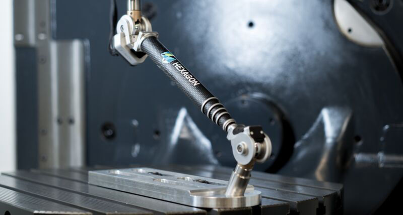
The X-AX LASERBAR is the solution to calibrate 3- 5-axis machine tools completely with minimal measuring equipment expenditure. A measuring system for determining volumetric machine deviations has never been so compact, light and inexpensive.
Determination of the quality-relevant axis geometry for linear axes: straightness, pitch, yaw, roll, positioning (6 DOF) + squareness, up to axis lengths of 1.5 m.
Determination of the quality-relevant axis geometry for rotary axes: axial and radial runout, wobble and angular positioning (6 DOF) + orientation.
Monitoring of machines, flexibly and independently.
Simple measurement and documentation.
Savings in time and effort for measuring equipment.
Output of compensation data per mouse click.
Optional volumetric compensation for maximum accuracy gain.
Standard-compliant machine verification.
Can be used anywhere.
As with the LASERTRACER, purely interferometric measurements are used to determine the geometric condition of the machine. With the X-AX LASERBAR, the laser is guided from the machine via the multi-stage telescopic tube. The two ends are supported by precision spheres in sphere nests. This makes it possible to calibrate smaller and medium-sized machine tools with 3, 4, 5 or more axes with manageable hardware.
With conventional measuring equipment, the total geometric deviations of a 5-axis machine can only be determined with extremely high effort – the entire process can take several days. Etalon’s X-AX LASERBAR, on the other hand, requires no more than two to four hours to fully capture all geometrical deviations of a 5-axis machine.
Combined with the sophisticated TRAC-CAL software, the measuring system analyzes the entire working area of the machine tool. It provides an accuracy of 1 µm and determines position deviations, straightness deviations, rotational deviations (pitch, yaw, roll) and the perpendicularity of the axes to each other. The angular positioning deviations, the axial and radial movements and the wobbling of rotary axes are also fully recorded. At the push of a button, a corresponding measurement report is generated for documentation purposes.
To increase the accuracy of the machine, correction data can then be automatically generated for the control system. The result: a maximum reduction of all geometrical errors, a process stable production from the first component and thus hardly any rejects or reworking effort.
By filling out this form, you accept the terms of the Agreement on the use of the site, including with regard to the processing and use of personal data
Built with Mobirise
Free Offline Web Page Builder